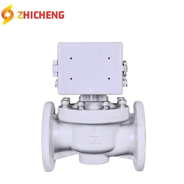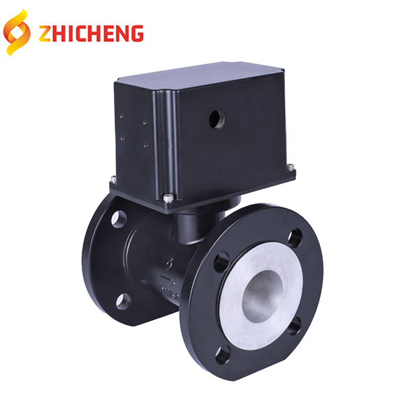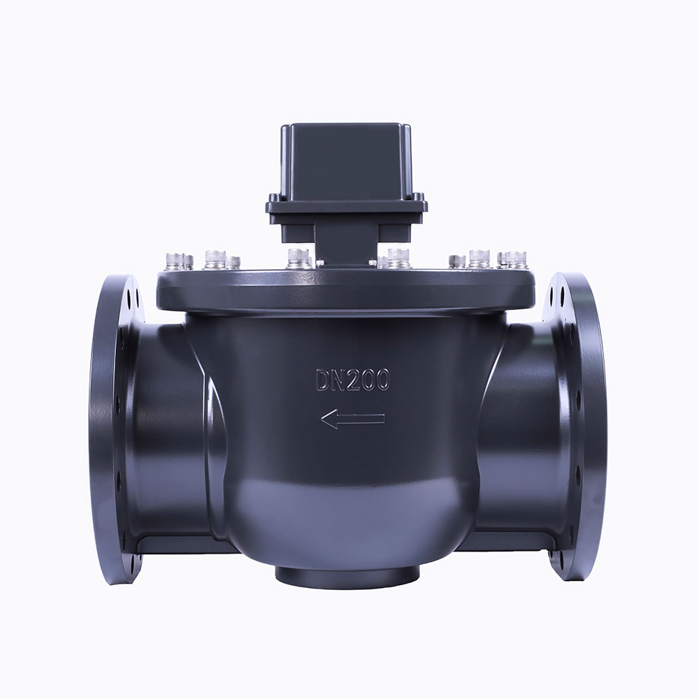
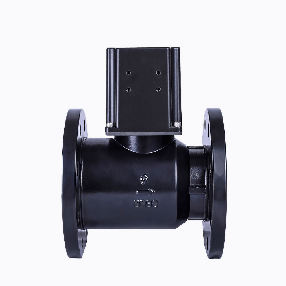
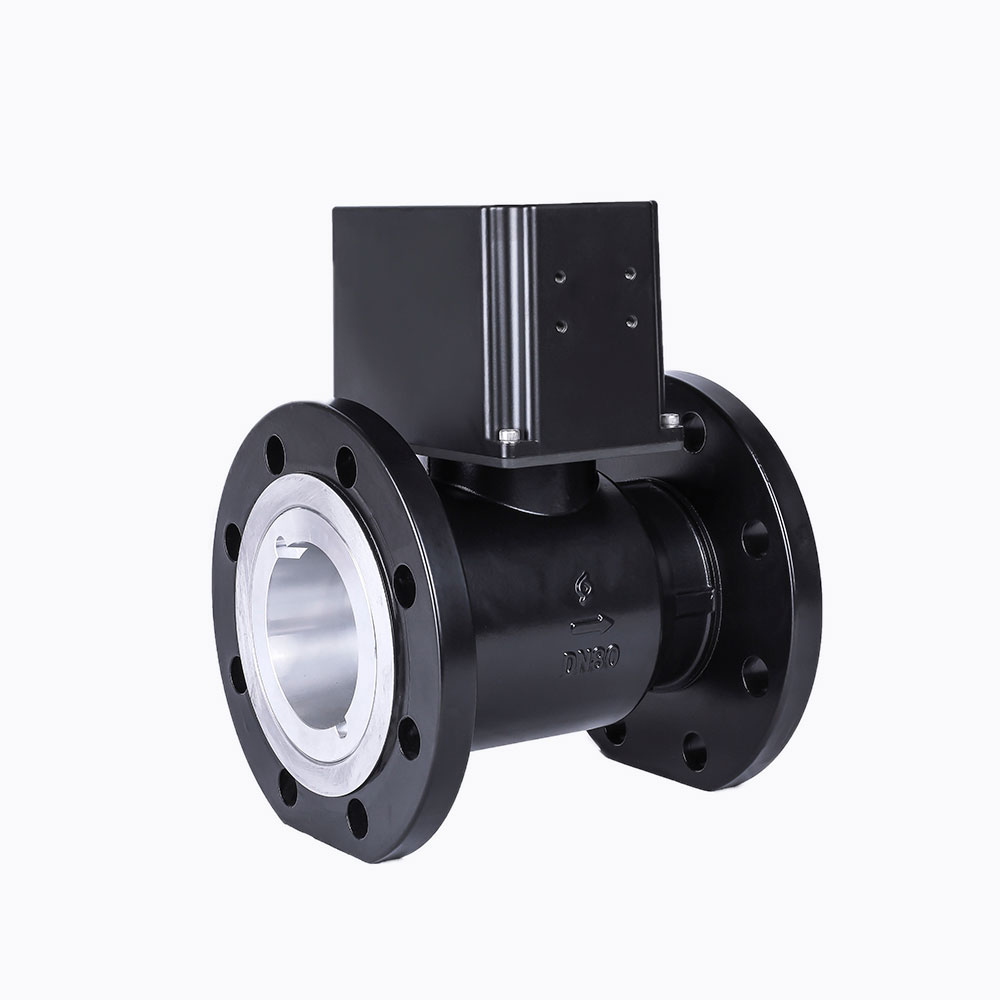
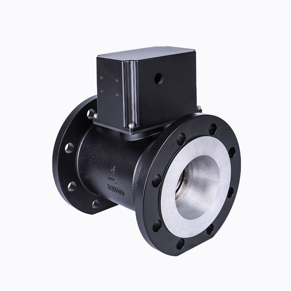
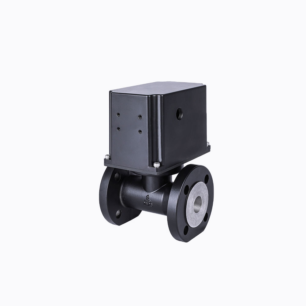
Pipeline Motor Floating-ball Valve
Installation location
The floating-ball valve can be installed on the gas pipeline

Product Advantages
Gas pipeline ball valve’s feature and advantages
1. The working pressure is large, and the valve can be opened and closed stably in the working environment of 0.4MPa;
2. The valve opening and closing time is short, and the valve opening and closing time is less than or equal to 50s under the limit working voltage of 7.2V;
3. There is no pressure loss, and the zero pressure loss structure design with the valve diameter equal to the pipe diameter is adopted;
4. The sealing performance of the closing valve is good, and the seal is made of nitrile rubber with high temperature resistance (60℃) and low temperature (-25℃).
5. With limit switch, it can accurately detect the in-position status of the switch valve;
6. The on-off valve runs smoothly, without vibration and with low noise;
7. The motor and gear box are fully sealed, and the protection level is ≥IP65, which completely prevents the transmission medium from entering, and has good explosion-proof performance;
8. The valve body is made of aluminum, which can withstand 1.6MPa pressure, resist shock and vibration, and adapt to complex environments;
9. The surface of the valve body is anodized, which is beautiful and clean and has good anti-corrosion performance;
Instruction For Use
1. The red wire and the black wire are the power wires, the black wire is connected to the positive electrode, and the red wire is connected to the negative electrode to open the valve;
2. Optional in-position signal output lines: 2 white lines are the valve-open in-position signal lines, which are short-circuited when the valve is in place; 2 blue lines are the valve-close in-position signal lines, which are short-circuited when the valve is in place; (After the valve is opened or closed, the power supply is usually extended for 5s to ensure the stability of the in-position signal)
3. The deceleration box of the valve can be rotated 180 degrees as a whole according to the convenience of the customer to install the control box, and the valve can be used normally after rotation;
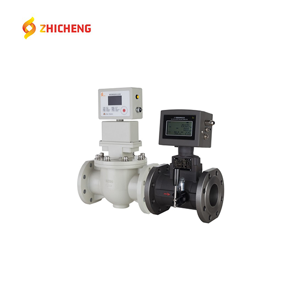
4. Use standard flange bolts to connect valves, pipes, and flowmeters. Before installation, the end face of the flange should be carefully cleaned to prevent iron slag, rust, dust and other sharp objects on the end surface from scratching the gasket and causing leakage;
5. The valve should be installed in the pipeline or flowmeter with the valve closed. It is strictly prohibited to use it in the state of overpressure or gas leakage and to detect leakage with open fire;
6. The appearance of this product is provided with a nameplate.
Tech Specs
|
No.号 |
Itrms |
Requirement |
||||
|
1 |
Working medium |
Nature gas LPG |
||||
|
2 |
Nominal diameter(mm) |
DN25 |
DN40 |
DN50 |
DN80 |
DN100 |
|
3 |
Pressure range |
0~0.4Mpa |
||||
|
4 |
Nominal pressure |
0.8MPa |
||||
|
5 |
Operating Voltage |
DC3~7.2V |
||||
|
6 |
Operating current |
≤50mA(DC4.5V) |
||||
|
7 |
Max current |
≤350mA(DC4.5V) |
||||
|
8 |
Blocked current |
≤350mA(DC4.5V) |
||||
|
9 |
Operating temperature |
-25℃~60℃ |
||||
|
10 |
Storage temperature |
-25℃~60℃ |
||||
|
11 |
Operating humidity |
5%~95% |
||||
|
12 |
Storage humidity |
≤95% |
||||
|
13 |
ATEX |
ExibⅡB T4 Gb |
||||
|
14 |
Protection class |
IP65 |
||||
|
15 |
Opening time |
≤60s(DC7.2V) |
||||
|
16 |
Closing time |
≤60s(DC7.2V) |
||||
|
17 |
Leakage |
Under 0.4MPa, leakage ≤0.55dm3/h(compress time 2min) |
||||
|
Under 5KPa, leakage≤0.1dm3/h(compress time2min) |
||||||
|
18 |
Motor risistance |
21Ω±3Ω |
||||
|
19 |
switch contact resistance |
≤1.5Ω |
||||
|
20 |
Endurance |
≥4000 times |
||||
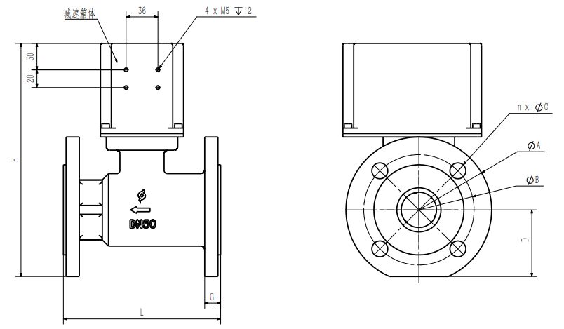
Structure Specs
|
Diameter |
L |
H |
ΦA |
ΦB |
n x ΦC |
D |
G |
|
DN25 |
140 |
212 |
Φ115 |
Φ85 |
4 x Φ14 |
51 |
18 |
|
DN40 |
178 |
246 |
Φ150 |
Φ110 |
4 x Φ18 |
67 |
18 |
|
DN50 |
178 |
262 |
Φ165 |
Φ125 |
4 x Φ18 |
76 |
18 |
|
DN80 |
203 |
300 |
Φ200 |
Φ160 |
8 x Φ18 |
91 |
20 |
|
DN100 |
229 |
317 |
Φ220 |
Φ180 |
8 x Φ18 |
101 |
20 |